
Flexible solar panels are often selected when a flat glass module cannot fit the available installation surface.
Typical applications include boat roofs, curved equipment housings, vehicle surfaces, outdoor electronics, portable systems, and custom enclosures.
But designing a solar panel for a curved surface is not simply a matter of making the panel thinner.
The curvature affects the solar cell layout, panel dimensions, encapsulation materials, mounting method, cable routing, and long-term mechanical reliability.
This guide explains the main engineering factors to consider when designing a flexible solar panel for curved surfaces.
Start With the Installation Surface
Before selecting solar cells or defining the panel size, the first step is to understand the actual installation surface.
A curved surface may be:
- Slightly curved in one direction
- Cylindrical
- Convex
- Concave
- Irregularly shaped
- Curved in more than one direction
These surfaces should not automatically be treated the same way.
A thin solar panel can normally follow a gentle curve in one direction more easily than a complex three-dimensional surface.
For custom projects, providing a 2D drawing, 3D model, CAD file, or actual installation dimensions can significantly improve the panel design process.
Key information to provide
For a curved-surface solar project, it is helpful to define:
- Available installation length and width
- Curvature direction
- Approximate bending radius
- Maximum available thickness
- Required power or charging target
- Mounting method
- Cable exit position
- Outdoor exposure conditions
The available surface should define the solar panel—not the other way around.
Understand Bending Radius
One of the most important parameters for a flexible solar panel is the bending radius.
The bending radius describes how tightly the panel needs to curve.
A larger radius means a gentler curve.
A smaller radius means the panel must bend more sharply.
This matters because the solar cells, PCB or backsheet structure, encapsulation layers, solder joints, and interconnections all experience mechanical stress when the panel bends.
Why excessive bending can cause problems
If a solar panel is bent beyond the limits of its structure, it may increase the risk of:
- Solar cell microcracks
- Broken interconnections
- Delamination
- Encapsulation stress
- Reduced electrical output
- Premature failure
The allowable bending radius therefore depends on the complete panel construction rather than the surface material alone.
For custom designs, the curvature should be confirmed before the cell layout is finalized.
Solar Cell Type Matters
The type and size of solar cells strongly influence how a panel can follow a curved surface.
Large solar cells provide good electrical efficiency, but they are also mechanically rigid.
Smaller cell pieces can often be arranged more effectively across curved or irregular surfaces.
This is especially important for compact custom solar modules.
Cell layout can be optimized by:
- Using smaller cell segments
- Changing the number of cells in each row
- Adjusting spacing between cells
- Changing the direction of the cell strings
- Separating the active area into multiple sections
For some applications, the goal is not simply to fit the largest possible solar cell.
The better approach is to balance:
Available Area → Curvature → Cell Layout → Voltage → Power
This can result in a more reliable design.
Avoid Placing High-Stress Areas Across Solar Cells
When designing a panel around a curved surface, it is important to understand where the panel experiences the greatest bending stress.
Ideally, the strongest curvature should not pass directly through the most mechanically sensitive areas of the solar cells.
Where possible, the cell layout can be adjusted so that:
- Bending occurs between cell areas
- Interconnection zones remain relatively stable
- Solder joints are not located at high-stress points
- Large rigid components are kept away from bending zones
This becomes especially important for long and narrow flexible panels.
Panel Construction Affects Flexibility
Not all flexible solar panels have the same mechanical structure.
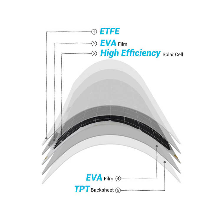
A typical lightweight custom module may include:
- ETFE front layer
- EVA or another encapsulation layer
- Solar cells
- Flexible or semi-flexible substrate
- Rear protective layer
- Adhesive or mounting layer
Each material contributes to the final thickness, stiffness, weather resistance, and bending performance.
ETFE is commonly used for outdoor flexible modules
ETFE is frequently selected because it offers:
- Low weight
- Good outdoor weather resistance
- UV resistance
- Textured surface options
- Good protection for lightweight solar modules
However, using ETFE does not automatically mean that a solar panel can be folded or repeatedly bent.
There is an important difference between:
Flexible
and
Most custom flexible solar modules are designed to conform to a curved installation surface during installation.
They are not intended to be repeatedly folded back and forth during operation.
Static Curvature vs. Repeated Flexing
This is one of the most important distinctions in flexible solar panel design.
Static curved installation
The panel is bent gently during installation and then remains fixed in that shape.
Examples include:
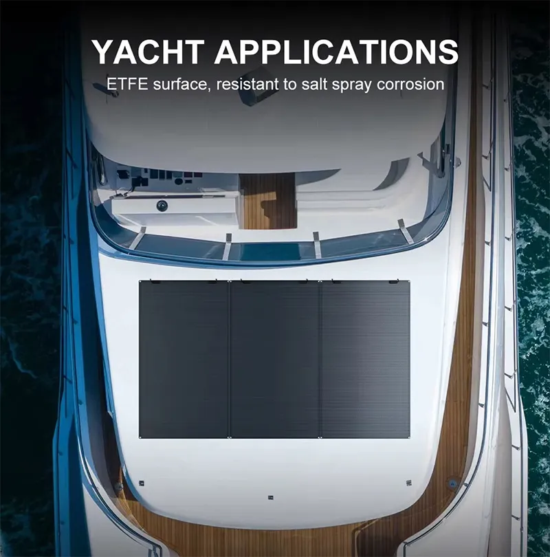
- Boat roofs
- Vehicle roofs
- Curved equipment enclosures
- Outdoor control boxes
- Custom housings
This is the more common use case for flexible solar panels.
Repeated dynamic bending
The panel is continuously bent, folded, rolled, or moved during operation.
Examples include:
- Foldable equipment
- Moving mechanical structures
- Repeatedly rolled solar products
These applications require a different mechanical design and should be evaluated separately.
A solar panel that works well on a permanently curved surface may not be suitable for continuous flexing.
Mounting Method Is Part of the Solar Panel Design
For curved surfaces, mounting cannot be considered only after the panel has been manufactured.
The mounting method affects the panel dimensions, mechanical stress, edge structure, and long-term reliability.
Common mounting methods include:
Adhesive mounting
This is commonly used for:
- Vehicle surfaces
- Equipment housings
- Smooth curved structures
- Lightweight outdoor devices
Possible options include industrial double-sided adhesive or structural adhesive, depending on the application.
The installation surface should be clean, stable, and suitable for bonding.
Screw mounting
Mounting holes can also be designed into some custom solar panels.
However, holes reduce the available area for solar cells and introduce additional mechanical constraints.
If mounting holes are required, their position should be defined before the cell layout is designed.
Integrated housing installation
For OEM projects, the solar panel can sometimes be designed to fit directly into a recessed area or product housing.
This can provide better positioning and a cleaner finished appearance.
Avoid Local Pressure Points
A flexible panel should normally be supported by a smooth surface.
Small raised points, screw heads, sharp edges, uneven adhesive layers, or surface debris can create concentrated mechanical pressure.
Over time, these pressure points may increase the risk of cell damage.
The installation surface should therefore be:
- Smooth
- Clean
- Free from sharp edges
- Structurally stable
- Properly matched to the panel shape
A flexible panel can adapt to a curve.
It should not be expected to compensate for a poorly prepared mounting surface.
Consider Thermal Expansion
Outdoor solar panels experience repeated heating and cooling.
A panel installed on metal, plastic, fiberglass, or another substrate may expand at a different rate from the mounting surface.
This can create mechanical stress between:
- Solar panel
- Adhesive
- Substrate
- Cable connections
For larger curved panels, thermal movement should be considered when choosing both the mounting method and panel structure.
This is particularly important in applications exposed to direct sunlight for long periods.
Cable Exit Position Should Be Planned Early
Cable routing is often overlooked during the early stage of a custom solar panel project.
On a curved surface, however, the cable exit location can influence the entire installation.
The cable may exit from:
- Rear center
- Rear edge
- Side
- Custom position
The correct location depends on the enclosure and available routing space.
Whenever possible, connectors, solder points, and cable exits should be positioned away from the main bending area.
For integrated products, defining the cable location during the initial CAD stage can prevent later installation problems.
Power Expectations Need to Match the Available Curved Area
For many custom projects, the available surface area is fixed.
The required output may not be.
This creates an important engineering question:
Can the available curved surface provide enough solar energy for the system?
The answer depends on:
- Available active area
- Solar cell efficiency
- Required operating voltage
- Battery capacity
- Power consumption
- Daily solar exposure
- Charging strategy
For battery-powered IoT and outdoor electronic products, it is usually better to evaluate the complete energy system instead of specifying only a target solar-panel wattage.
The design sequence should ideally be:
Device Load → Battery → Charging Strategy → Available Surface → Solar Panel Design
Partial Shading Can Be More Important on Curved Surfaces
A curved solar panel may not receive uniform sunlight across its entire surface.
One section may face the sun directly while another section receives light at a different angle.
Structures around the panel can also create partial shading.
Depending on the application, the electrical layout may need to consider:
- Cell string arrangement
- Panel orientation
- Shading direction
- Separate electrical sections
- Bypass protection
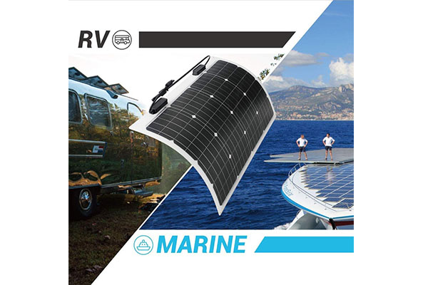
This is particularly relevant for marine, vehicle, and equipment-mounted solar systems.
Curved Surface Design Example
Consider a customer developing a solar-powered outdoor device with a curved upper housing.
The customer knows:
- Housing dimensions
- Battery voltage
- Daily energy consumption
- Available curved surface
Instead of choosing a standard rectangular solar panel first, the solar module can be developed around the housing.
The engineering process may look like this:
Step 1 — Define the available curved area
Confirm the usable surface and curvature.
Step 2 — Confirm electrical requirements
Understand battery voltage, charging circuit, and required solar contribution.
Step 3 — Create the cell layout
Select suitable solar cells and arrange them within the available surface.
Step 4 — Optimize mechanical structure
Confirm thickness, encapsulation, bending direction, and mounting method.
Step 5 — Confirm cable position
Match the output cable or solder pads to the device enclosure.
Step 6 — Build and test prototypes
Check fit, electrical output, appearance, and installation before mass production.
This approach usually produces a better result than trying to modify an existing standard solar panel after the product enclosure has already been finalized.
Information We Recommend Sending to Your Solar Panel Supplier
If you are developing a solar panel for a curved product, prepare as much of the following information as possible:
| Design Information | Why It Matters |
|---|---|
| CAD or dimensional drawing | Defines available solar area |
| Surface curvature | Determines mechanical design |
| Bending direction | Helps optimize cell orientation |
| Minimum bending radius | Helps evaluate panel construction |
| Battery specification | Determines electrical design |
| Charging voltage | Defines required panel voltage |
| Required power | Determines active cell area |
| Installation method | Affects panel edge and structure |
| Cable exit position | Prevents installation conflicts |
| Operating environment | Helps select suitable materials |
| Expected quantity | Helps evaluate prototype and production process |
Even when all parameters are not available, the panel supplier can often help develop the specification step by step.
Common Design Mistakes
Several problems appear repeatedly in curved-surface solar projects.
Mistake 1: Designing the solar panel before confirming the curvature
A flat drawing alone may not show the mechanical stress the panel will experience.
Mistake 2: Assuming “flexible” means unlimited bending
Every solar panel structure has mechanical limits.
Mistake 3: Using the largest possible cells
Smaller or differently arranged cells may produce a more reliable panel on a curved surface.
Mistake 4: Adding mounting holes after the cell layout is finished
Mounting holes require space and may force the entire cell arrangement to change.
Mistake 5: Ignoring cable routing
A poorly positioned cable can make an otherwise correct solar panel difficult to install.
Mistake 6: Evaluating only watts
The solar module must work together with the battery, charging circuit, installation angle, and energy consumption.
Engineering Takeaway
Designing a solar panel for a curved surface is mainly a mechanical and electrical integration problem.
The key is not to ask:
“How flexible can the solar panel be?”
A better question is:
“How should the solar panel be designed around this specific surface?”
The most reliable design normally starts with the installation geometry, battery system, electrical requirements, and mounting conditions.
From there, the cell layout, encapsulation structure, thickness, cable position, and panel shape can be optimized together.
Need a Custom Solar Panel for a Curved Surface?
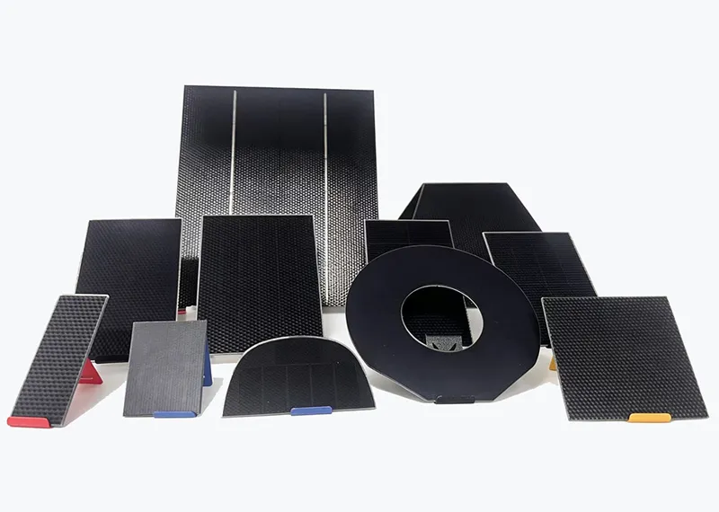
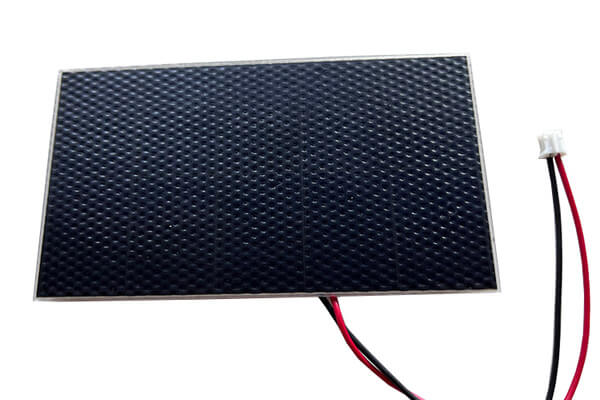
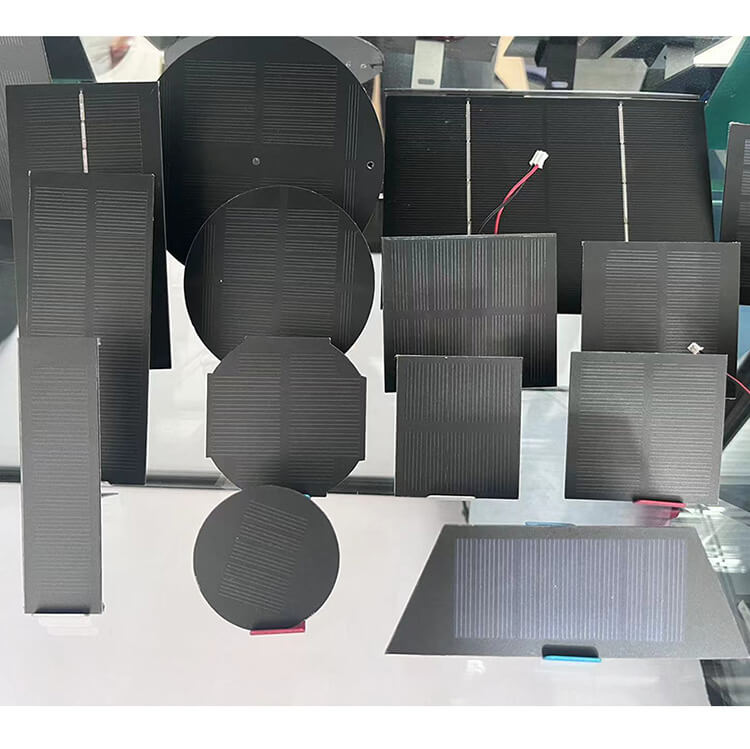
XRSOLAR develops custom solar panels for OEM and industrial applications, including curved and space-limited installation surfaces.
We can customize:
- Panel size and shape
- Voltage and power
- Solar cell type
- ETFE surface structure
- Thickness
- Cable position
- Solder pads and connectors
- Mounting holes
- Adhesive backing
If you already have a CAD drawing, enclosure drawing, battery specification, or installation dimensions, send them to our engineering team.
We can evaluate the available area and help develop a solar panel around your product.
0 Comments