
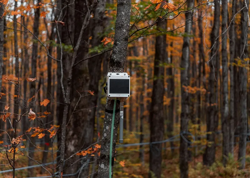
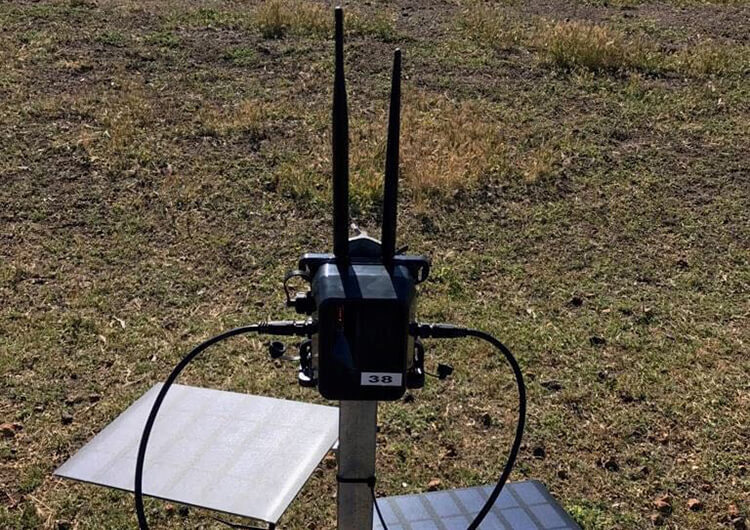
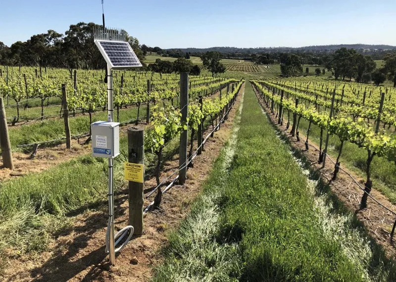
Outdoor environmental sensing systems are often installed in locations where access to grid power is limited or unavailable.
Weather monitoring equipment, environmental sensors, remote data collection devices, and other field instruments may need to operate continuously while being exposed to changing outdoor conditions.
For these applications, selecting a solar panel is not simply a matter of choosing the required wattage.
The solar module also needs to fit the equipment mechanically and connect correctly to the customer’s charging and power-management system.
In this case study, we look at a customized 10W 18V ETFE solar panel platform developed for outdoor environmental sensing applications—and how the same core solar module can be adapted with different cable and connector configurations for different customer devices.
Project Background
The application is an outdoor environmental sensing system requiring a compact solar module for off-grid or solar-assisted operation.
The core solar-panel requirements included:
- Approximately 10W power output
- 18V-class operating voltage
- Compact module dimensions
- ETFE construction
- PCB-backed structure
- Outdoor installation
- Mechanical mounting holes
- Customized cable and connector options
The final module design is based on the XRSOLAR XR-HSM223274-16-01E platform.
Its electrical specifications include:
Pmax: 9.77W
Vmp: 17.6V
Imp: 0.56A
Voc: 21.12V
Isc: 0.65A
The module dimensions are 223 × 273.5 × 3.6mm ±0.3mm. XR-HSM223274-16-01E datasheet
Although we refer to the module as a 10W 18V ETFE solar panel for easier product classification, the actual electrical values are defined by the module specification.
The Design Challenge
At first glance, the project appears straightforward:
10W + 18V + ETFE
But these three specifications do not define the complete solar module.
For an outdoor sensing system, the module also needs to answer several integration questions:
How much installation area is available?
How will the panel be mounted to the equipment?
Where should the cable exit?
What connector does the customer’s device use?
Does the connector need additional outdoor protection?
This means the project needs to consider three design layers together:
Electrical Design → Mechanical Design → Device Interface
Electrical Design: 10W-Class Output in a Compact Area
The module uses 32 solar cells arranged in a 4 × 8 layout.
The individual solar-cell size is approximately 30 × 52.25mm, and the specified solar-cell efficiency is greater than 23%. XR-HSM223274-16-01E datasheet
The final electrical configuration provides:
| Electrical Parameter | Specification |
| Maximum Power (Pmax) | 9.77W |
| Maximum Power Voltage (Vmp) | 17.6V |
| Maximum Power Current (Imp) | 0.56A |
| Open Circuit Voltage (Voc) | 21.12V |
| Short Circuit Current (Isc) | 0.65A |
For an outdoor sensing project, voltage and power should not be considered independently from the customer’s charging electronics.
The solar module needs to operate within the requirements of the complete system, including the battery and charging controller.
Engineering Note: Before finalizing solar-panel voltage, we recommend confirming the and maximum permitted input voltage.charging controller’s PV input voltage range
ETFE + PCB Construction for Product Integration
The module uses the following structure:
ETFE Film → EVA → Solar Cell → EVA → 2.5mm PCB Backing
This results in a finished module thickness of approximately 3.6mm ±0.3mm. XR-HSM223274-16-01E datasheet
For this type of customized outdoor electronic application, the PCB backing provides a defined module structure while also allowing the solar module to be manufactured in relatively compact dimensions.
The finished module measures:
223 × 273.5 × 3.6mm
This makes the solar panel easier to integrate into equipment where the available installation surface has already been defined.
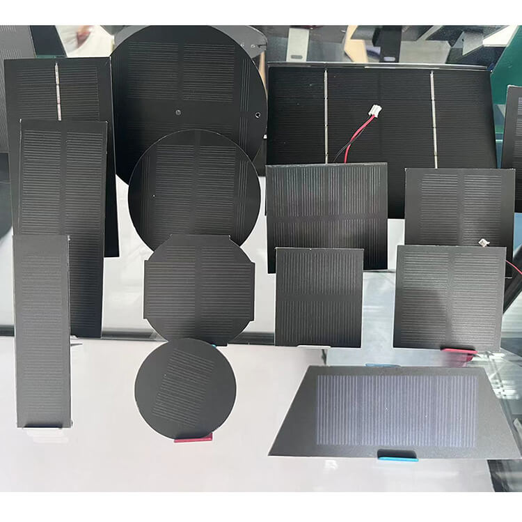
Instead of designing the equipment around a standard commercial solar panel, the solar module can be developed around the product’s available area and electrical requirements.
Mechanical Mounting Is Part of the Solar Panel Design
The module is not designed only around electrical output.
Its mechanical interface also needs to match the customer’s equipment.
The engineering drawing for this module includes mounting holes around the perimeter of the PCB-backed panel, allowing the module to be mechanically integrated with the customer’s equipment structure. The dimensional drawing also defines the front and back layout of the panel.
This is an important consideration for outdoor equipment.
Mounting holes should ideally be considered during the solar-panel design stage rather than added after the electrical layout has already been finalized.
Their position may influence:
- Available cell-layout area
- PCB dimensions
- Edge spacing
- Cable routing
- Equipment alignment
- Installation tolerances
For customized solar modules, electrical and mechanical requirements should therefore be developed together.
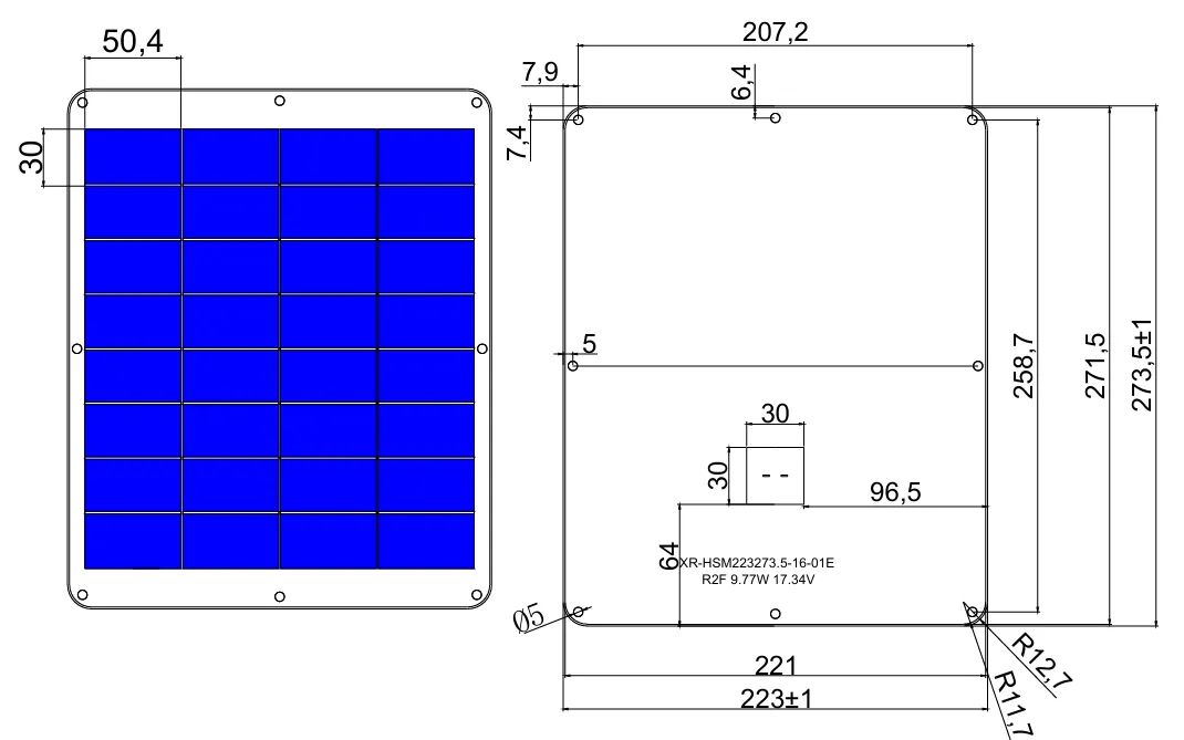
Mechanical dimensions and mounting-hole positions are defined together with the solar module layout for equipment integration.
One Solar Module, Different Connector Requirements
One of the most useful lessons from this solar module platform is that the core panel specification can remain the same while the cable and connector configuration changes between customer projects.
Different environmental sensing systems may use different:
- Equipment enclosures
- Charging controllers
- Internal wiring
- External interfaces
- Cable-routing methods
- Environmental protection strategies
For this reason, we do not need to define one connector as the only standard configuration for the module.
Depending on the project, customers have used configurations such as:
Waterproof Male/Female Connector
A waterproof connector can be selected when the connection point is exposed to the outdoor environment and the system requires a protected detachable connection.
DC Connector
Some equipment already uses a standard DC power interface.
In these projects, configuring the solar module with the appropriate DC connector can simplify integration with the existing device.
Molex Micro-Fit 3.0 Connector
For equipment using an internal wiring harness or compact electrical interface, a Molex Micro-Fit 3.0 connector can be configured according to the customer’s device requirements.
Cable length and output configuration can also be adjusted according to the installation method.
Engineering Note: A solar panel can have the correct voltage and power but still be difficult to integrate if the cable length, connector type, polarity, or output position does not match the device.
This is why we consider the cable and connector part of the solar module integration design, rather than an accessory selected at the end of the project.
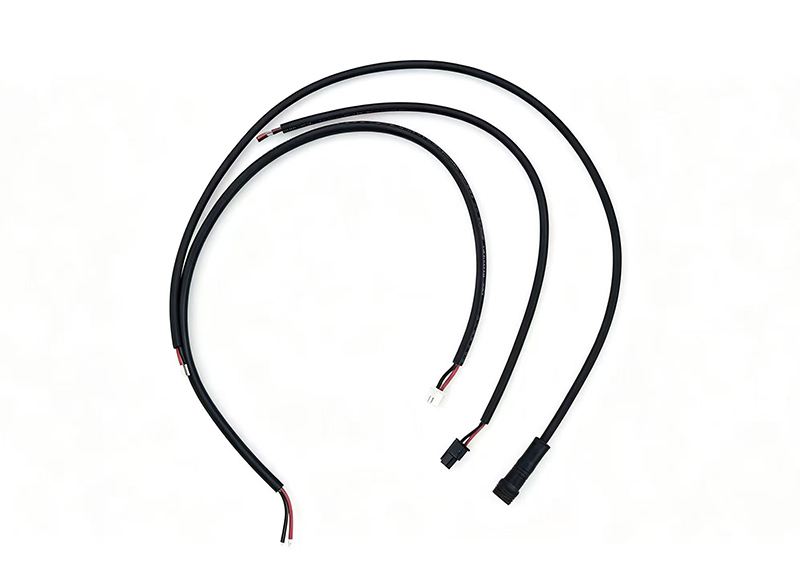
One Solar Module — Customized for Different Device Interfaces
Outdoor Protection Includes More Than the Solar Panel
For outdoor sensing equipment, waterproofing should not be considered only at the solar-panel surface.
According to the module specification, the ETFE solar panel has passed an IP67 waterproof test, excluding the connector. XR-HSM223274-16-01E datasheet
This distinction is important.
The solar module and electrical connector are different parts of the complete environmental protection system.
A project may therefore need to consider:
Solar Module Protection
- ETFE surface
- Lamination
- Edge sealing
- Cable output area
and separately:
Connection Protection
- Connector type
- Connector sealing
- Cable routing
- Connection location
- Customer enclosure
For example, a waterproof male/female connector may be appropriate when the electrical connection is exposed outdoors.
Another project may use a DC or Molex connector because the connection is located inside a protected equipment enclosure.
Therefore:
The appropriate connector depends on where and how the solar module connects to the device.
This is another reason why the application environment and equipment structure should be reviewed before finalizing the solar-panel configuration.
6. Final Solar Module Specification
The resulting module platform combines the electrical requirements of a 10W-class, 18V solar panel with the mechanical flexibility needed for outdoor sensing equipment.
| Specification | Final Design |
| Model | XR-HSM223274-16-01E |
| Application | Outdoor Environmental Sensing System |
| Power Class | 10W |
| Maximum Power (Pmax) | 9.77W |
| Maximum Power Voltage (Vmp) | 17.6V |
| Maximum Power Current (Imp) | 0.56A |
| Open Circuit Voltage (Voc) | 21.12V |
| Short Circuit Current (Isc) | 0.65A |
| Module Size | 223 × 273.5 × 3.6mm ±0.3mm |
| Cell Type | BC Solar Cell |
| Cell Size | 30 × 52.25mm |
| Cell Layout | 32 cells / 4 × 8 |
| Construction | ETFE + EVA + Solar Cell + EVA + 2.5mm PCB |
| Solar Cell Efficiency | >23% |
| Connector | Customized by project |
| Connector Options | Waterproof / DC / Molex Micro-Fit 3.0 |
| Cable Length | Customized by project |
| Output Tolerance | ±10% |
The core electrical, dimensional and construction values above are based on the module datasheet.
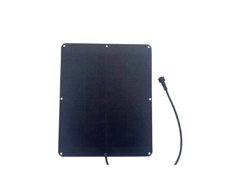
What Can Be Customized?
This project also demonstrates that a custom solar module is not defined only by wattage and voltage.
Depending on the application, the module design can be adjusted around:
Electrical Requirements
- Voltage
- Power
- Cell configuration
Mechanical Requirements
- Module dimensions
- PCB thickness
- Mounting-hole positions
- Cable output position
Device Interface
- Cable length
- Connector type
- Polarity
- Wiring configuration
Application Requirements
- Installation method
- Outdoor environment
- Equipment enclosure
- Available solar area
For outdoor electronics, these parameters should be considered together rather than independently.
Engineering Takeaway: Design the Solar Module Around the Device
The main lesson from this project is simple:
A custom solar panel is not defined by wattage alone.
The same core 10W 18V ETFE solar module can require different integration details depending on the customer’s equipment.
One device may require a waterproof connector.
Another may use a DC interface.
Another may need a Molex Micro-Fit 3.0 connector integrated into its internal wiring system.
At the same time, the solar module still needs to meet the required:
Voltage → Power → Dimensions → Mounting → Cable → Connector
This is why the most effective custom solar projects begin with the device requirements—not with a standard solar-panel catalog.
Design the solar module around the equipment, not the equipment around the solar module.
Developing an Outdoor Environmental Sensing System?
XRSOLAR develops customized solar modules for:
- Environmental sensing systems
- Remote monitoring equipment
- Outdoor IoT devices
- Weather monitoring equipment
- Smart agriculture systems
- Other battery-powered outdoor electronics
For an initial engineering evaluation, send us:
Device Power + Battery Information + Controller PV Input Range + Available Solar Area + Mounting Requirements + Connector Requirements
Based on these requirements, we can evaluate the appropriate:
Voltage • Power • Dimensions • Cell Layout • Module Construction • Cable • Connector
0 Comments